Airsoft Gun Wiring Repairs
Airsoft gun wiring plays a very important role in the optimal functionality of all automatic AEGs. Currently, some models come packed with beautifully intricate electronic Mosfets and triggers. However, today, what I’ll be addressing is the general wiring of an Airsoft AEG and the associated components. These include:
- Fuses
- Battery connections
- Motor connections
- Standard trigger contact shuttle and the complete contact system
- The AEG wiring that completes the circuit
Fuses
When you get to the electrical circuit of an AEG, you are going to find some sort of fuse link and a fuse holder. In general, Airsoft factories use 15 amp fuses in order to protect the circuit of the motor. In case your motor fails when you fire the trigger, the first diagnostic step is checking your battery and fuse connection. In case you upgraded your gun for a higher FPS with high torque motors, you may have had to take the fuses out for ideal operation. However, if you use them or you are a little concerned about your setup, here are two great options for you.
- Plastic or glass automotive fuse: you will find them in the majority of stock AEGs out there. In case they trip, you just replace it by popping another one in.

Figure : AEG Plastic blade type fuse
Source: havarhen, Electrical fuses, plug-in type, different sizes, CC BY-SA 3.0
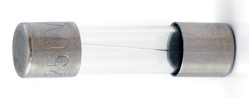
Figure : Glass fuse
Source: Aka, Glassikring, CC BY-SA 2.5
- Resettable/Polyfuses: when heated,these types expand gradually to such a point that they can’t conduct electricity any more. After the circuit is broken and current is no longer flowing, they cool and contract to a point where they can conduct current once again. Nonetheless, after they trip for the first time, they easily trip again unless you give them enough cooling time.
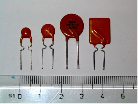
Figure : Resettable Polyfuse
Source: By Shaddack (Own work) [Public domain], via Wikimedia Commons
Connections
- Battery Connections
In electric Airsoft guns such as the Firepower F4-D AEG, the connections essentially begin at the battery, located on the butt stock or at the front grip, depending on your model. There are two main battery connections that are used depending on your gun’s model. They are:
- Pin/Tamiya plug connector – Have lighter contacts with lower amperage rating. These are much more susceptible to loosen up and will likely lead to recurrent repairs since they wear out after roughly 50 cycles.
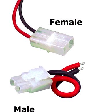
Figure : Tamiya Plug Connector
Source: By Blackeagle2001 at English Wikipedia [Public domain], via Wikimedia Commons
- T-Type/Deans plug connectors – The contacts are much heavier since they have a higher amperage rating of between 30-40 amps. This translates to less resistance and thus, a cooler running motor
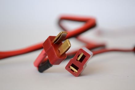
Figure T-Type/Deans Connector:
Source: KundaliniZero, Deans connector 1, CC BY-SA 3.0
How to add the T-Type/Deans plug connectors
If you are tired of the recurrent repairs of the Pin/Tamiya plug connector, here is how you can replace them with the much better T-Type/Deans plug connectors.
Technical Outline
- OBJECTIVE: Adding the T-Type/Deans plug connectors
- DIFFICULTY LEVEL (on a scale of 1-10): 6
- DURATION: 20-30 minutes
Required Tools
- Soldering iron
- Flux
- Sandpaper
- Heat shrink tubing
- Wire Strippers
- Pliers
Required Replacement Parts
- T-Type/Deans plug connectors
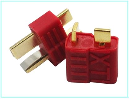
Figure T-Type/Deans Connector
Source: .tirnado, T-plug, CC BY-SA 3.0
Procedure
STEP A:
Cut off the Tamiya Plug connectors. In case this is the battery, ensure that you only cut off a single lead at a time so that you can avoid a short circuit. You can also use a clip or vice to clamp the Deans plug to hold it as you solder. In most cases, the male end is connected to the AEG harness and the female end goes to the battery.
STEP B:
Next, fix in each of the terminals of the Deans plug by adding a solder bubble to each of the tabs of the terminal
STEP C:
From there, place a heat shrink piece on each of the wires that are to be soldered and join the positive (+) wire to the perpendicular tab and join the negative wire to the flat tab.
- Motor Connections
Moving to the hand grip, you will find the motor and its wire terminals which connect it (the motor) to the wire harness. Sometimes due to vibrations, these terminals may end up getting lose from the motor, causing a short circuit that causes motor failure. To prevent these shorts, the gun motor terminals should be tightly fitted and properly insulated. There are three main options for motor connectors:
- Standard Motor Connectors: have very high resistance and thus, they aren’t the best choices.
- Gold Plated Motor Connectors: these allow for increased contact between the connector and the tab of the motor and thus the resistance reduces significantly.
- Directly Soldered Connectors: the wire is directly soldered to the motor tab. These are the best options especially since the resistance is minimal. However, every time you remove the motor, you have to de-solder them.
Trigger Contact Shuttle and the Contact System
When you go inside the gearbox you will find the contact shuttle and the trigger contacts. Only the red (+) wire should be connected across the switch. In older AEG circuits, the selector plate is used as a point of contact too. When running maintenance of your electric gun, check the contact assembly’s return spring and clean the contact surfaces in case they have a noticeable carbon build up or any other visible kind of dirt. DO NOT scratch the contacts. Check for any pitting or burning and you can replace if need be. In case you plan on upgrading your AEG for heavy use situations or higher FPS, use higher temperature contacts and shuttle.
AEG Wire Selection
There is a vast selection of wires that you should consider using in your AEG depending on the advantages and disadvantages. Here’s a quick breakdown:
Solid Wire
Pros:
- Very thin
- Has low resistance
- Can handle higher amperage than an equivalent gauge stranded wire
- Very stiff and can easily be routed through the gearbox
Cons:
- Fragile
- Might be too stiff in some cases
Silicone Wire (Deans Wet Noodle)
Pros:
- Exceptionally low resistance
- Highly flexible
Cons:
- Pretty expensive
- Quite thick
- Tough to solder
- Its insulation tears easily
Hook-up Wire
Pros:
- Highly flexible
- Thinner than a regular silicone wire
- It’s very affordable and easy to find
- Pretty tough insulation
Cons:
- Its 16-gauge wire may sometimes be too thick for the V2 gearbox
- Its performance in low resistance and amperage is not sufficient
Teflon Coated Mil-spec Wire
This is the standard OEM wire in Tokyo Marui, Prometheus and Systema
Pros:
- Pretty strong insulation
- Exceptionally thin: a 16AWG Teflon wire is much thinner than any other kind of AEG wire
- Comes with a silver coated copper conductor
- Low resistance
- Quite stiff and can easily be routed through AEG bodies and gearboxes
Cons:
- Costly
- Not very forgiving in case you wrongly measure out the lengths
Wire Size
Wires are measured in the AWG (American Wire Gauge) system where the gauge number is inversely proportional to the size of wire. i.e. the larger the number, the smaller the wire. Basically, the size of the CONDUCTOR is the only aspect that determines the gauge and not the wire’s overall size.
Depending on the manufacturer of the Airsoft gun, the wires used may be PVC or silicone coated and in general, a 16 AWG wire is used and it can handle 75 amps. However, high end companies typically go for heavier 14 AWG wires while low end companies use 18 AWG wires which are lighter. In the USA, low resistance PVC coated wires are readily available and silicon wires can even be bought from hobby shops.
For the best performance of your Airsoft gun, the type of battery and voltage also play a crucial role, but that is a topic we’ll cover much deeper another day.
Step by Step Guide on How to Replace a Version 2(V2) Wiring Harness
Does it feel like your AEG starts having issues right when you are in the heat of the action? Well, in such a situation, what do you do? Instead of shifting your focus in some rather unfulfilling activities like binge watching a TV show, I will show you how can get your AEG up and running again in less than an hour. Whether you are having a serious mechanical problem or you are just looking to give it an interior upgrade, you will find this guide quite useful.
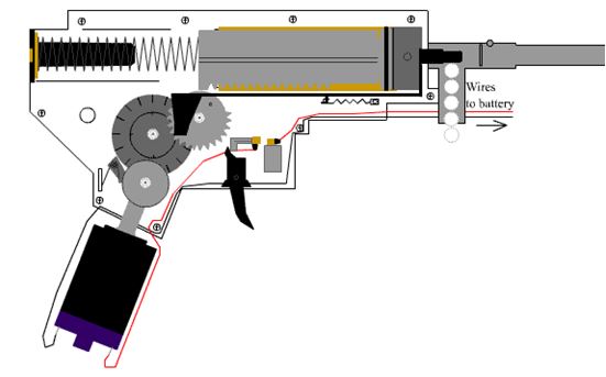
Figure : How a Version 2 Electric Motor Gearbox Works
Source: By Ranger Captain at English Wikipedia Later versions were uploaded by Boffy b at en.wikipedia. (Transferred from en.wikipedia to Commons.) [Public domain], via Wikimedia Commons
The process of diagnosing a harness problem may end up being quite difficult and for that reason, we’ll start by highlighting a couple of issues on a diagnostics checklist. So, if you have a damaged switch assembly, it could lead to issues such as;
- losses in the semi-automatic firing,
- an excessively long pull of the trigger, a runaway gun
- no firing at all.
If you experience any of the above issues, here are a couple of things you should do before anything else:
- Check the fuse and ensure that it is still intact and it works properly
- Confirm that the battery is fully charged
- Next, counter-check any of the gun’s connections. For instance, the motor connection. In some guns, an inline connector is placed in the wires for easier and faster dismantling either in the fore grip or stock.
- If everything else is right and things point to the AEG wire harness, you should just get it out; and the wire harness is what we’ll comprehensively cover in this dossier.
Here, we are going to take the V2 gearbox apart, identify the problems, fix them and put it back together. Since there are a wide range of ways in which each gun can be disassembled, let’s just jump right to the part of dismantling the gearbox. Let’s get right to it!
Technical Outline
- OBJECTIVE: To Replace the Wire Harness of an AEG
- DIFFICULTY LEVEL (on a scale of 1-10): 6
- DURATION: 40-50 minutes
Required Tools
- Flat head screwdriver
- P2 Phillips screwdriver (large)
- P1 Phillips screwdriver (small)
- 2mm hex for sliding into the spring guide when stabilizing the gearbox
Required Replacement Parts
- Wiring harness and V2 Plunger
- Raptors Airsoft DeepFire Switch Assembly
Procedure:
STEP A:
Start by taking off the bolt catch in case there is one. On this particular VFC gearbox, there is a bolt catch. Use the P1 screwdriver to dismantle it from its retaining screw. Be very keen so that you don’t lose the tiny spring that lies below. Just after that, undo all the other gearbox shell screws with the large screwdriver. Other gearbox brands may have 2mm Torx or hex type screws.
STEP B:
Disassemble the halves of the gearbox then take out the internal components. To prevent the spring guide from flying out, place a 2mm hex wrench through it then take off the top half of the gearbox using your other free hand. Place it aside then take the spring out slowly. After doing that, take out the piston, nozzle of the cylinder and the tappet all in one piece. Be careful not to lose the spring of the tappet. Remove the airsoft gears while staying on high alert to keep the gear shims in their proper place. After that, detach the AR (anti-reversal) latch and the spring.
STEP C:
Here comes the most interesting part; identifying the problem. Some of the things you should keep an eye out for in terms of damage include:
- The two brass tabs on your plunger assembly could be bent apart and thus not making proper contact with the plunger (the small movable part) itself
- The tabs could be fried completely
- Broken return spring on the upper section of the unit
- The tiny notch on the back side may be mashed up from the cut-off lever, thus preventing semi-auto
STEP D:
If you are lucky, you could shorten the pull on the trigger simply by pushing the two brass tabs slightly closer to each other to make the circuit close sooner. However, be careful not to overdo it since it could lock the plunger in place leading to much longer fires than ideal. On the other hand, in case the unit is in a poor condition, melted or completely fried, you will be better off when you replace it. If your wiring is still in great condition, just change this area by soldering out the old unit, fix the new unit in and solder it back to the wires.
STEP E:
In case you are replacing the new wires and wiring harness, make sure that you properly insert the wires in the gearbox. The wire that crosses the gap close to the motor should be kept beneath all the other wires. In addition, be sure to push the wires deep enough into the grooves when you set them but take caution so that you don’t strip them or damage them in any other way. If you damage them in that process, it could lead to a bunch of other problems such as damaging the new harness, your battery or even worse, the gun could catch fire on its own!
STEP F:
Confirm that you have secured all the parts properly and the leads of the motor are placed where they should be. The red wire should be at the front while the black wire is supposed to be at the back. You should also make sure that the right connector is also in place, whether you use Deans or Tamiya.
STEP G:
After everything is in place, reassemble the gearbox component and screw it up. Ensure that you align every component properly and that the shims are in their proper place. Gently tighten up the screws of the gearbox as well as the bolt catch.
STEP H:
To test the gearbox wiring, attach the power wires to the battery then connect the other end to the motor. To prevent the pinion gear from hitting stuff, hold the motor in place. Fire up the trigger and if the motor turns over, then everything is right, you can proceed with the assembly. In case the motor doesn’t turn over, counter-check all the connections and check to ensure that the plunger is able to slide at will in and out of the tabs of the trigger. If everything else checks out after that, continue re-assembling the remaining components of your AEG and you can hit the field again whenever you want.
Extra AEG Tips for Boosting Performance:
- Capacitor Banks
One of the best ways of boosting your rate of fire and trigger response, is by use of Capacitor Banks. Electrolytic capacitors are essential in the storage of energy and releasing in on demand. This is what will accommodate for the voltage drops that occur right after your initial pull of the trigger and when the AEG cycles through shots.
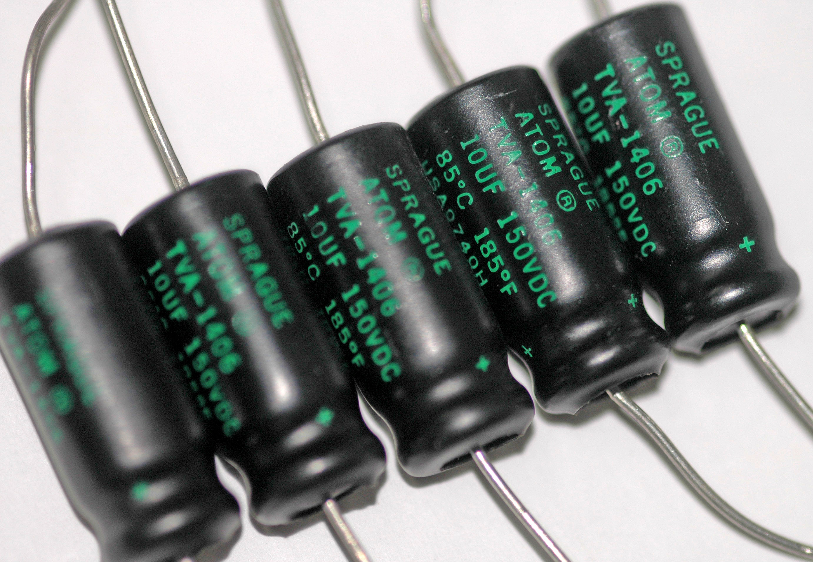
Figure : Axial Electrolytic Capacitors
Source: Mataresephotos, Axial electrolytic capacitors, CC BY 3.0
During the voltage drops, the capacitor will release its stored energy and thus smooth out the current. After the voltage drop passes, the capacitor will fill up again. However, the improvement is rather minimal and for a significant difference and you are going to need a pretty huge bank. You should however note that not all AEGs will have enough room for this extra fitting. If you have enough room to fit them in, there are virtually no downsides in using them.
How to Install a Capacitor Bank
Installation is quite simple, here is what you should do:
Step A:
Find a suitable location for them.
Step B:
Start soldering them in parallel connection to the circuit of your AEG wire system
Step C:
Since the capacitors are polarised, make sure you get the polarities right. If you aren’t sure, you can tell the negative (-) terminal by confirming that it has a stripe that runs down the cap on one side.
NOTE: Make your capacitor banks removable so that you can easily switch them from one gun to another.
- Mosfets
In AEGs, a mosfet is a switching transistor capable of handling high loads and transmits exceptionally low internal resistance. Some of the main benefits of mosfets include:
- Boost ROF
- Provides allowance for the use of batteries with higher voltages
- Prevents burning up of trigger contacts
- Enhance trigger response
- Powers up your electrical system’s overall efficiency
With some soldering skills, it is quite easy to make a Mosfet unit. Here’s how you can do it in easy steps.
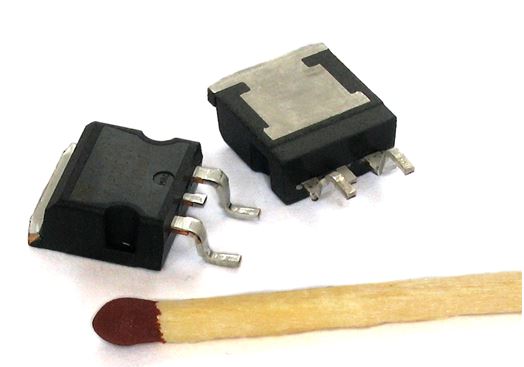
Figure : MOSFET
Attribution: CyrilB~commonswiki assumed (based on copyright claims)., D2PAK, CC BY-SA 3.0
How To Make and Add A Mosfet Unit
Technical Outline
- OBJECTIVE: To Make and add a Mosfet Unit to an AEG
- DIFFICULTY LEVEL (on a scale of 1-10): 7
- DURATION: 50 minutes – 1 hour
Required Tools
- Soldering iron
- Flux
- Sandpaper
- Heat shrink tubing (in various sizes)
- Wires (for the motor and gate) and Wire Strippers
- Voltmeter
- Glue Gun
- Heat Gun
- Helping Hand Tool
- Pliers
- Wet Cellulose Sponge
Required Parts
- Two 100Ω resistors
- Two 20-30kΩ resistors (pull-down resistors)
- A Suitable N-Channel Mosfet (ideally IRL1404z)
- N-channel and P-channel Mosfet (for AB system)

Figure : Resistor
Source: Nunikasi, Resistor, CC BY-SA 3.0
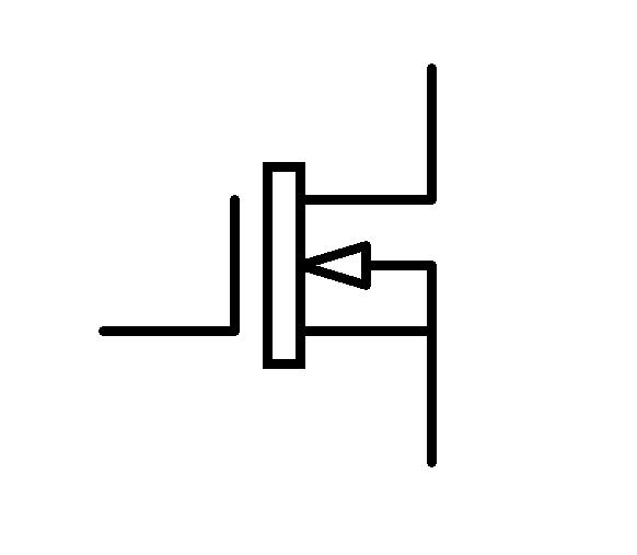
Figure : N-Channel Mosfet
Source: Marvelshine, Mosfet n, CC BY-SA 4.0
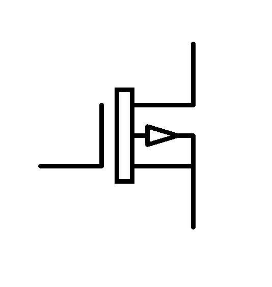
Figure : P-Channel Mosfet
Source: Marvelshine, Mosfet p, CC BY-SA 4.0
Procedure
STEP A:
Cover the Mosfets heatsink with heat-shrink tubing to prevent shorting anything just by touching it since the heatsink and the Drain pin contain an equivalent electrical value. Add some heat-shrink tubing to the pull-down resistor as well.
STEP B:
The Mosfet has three pins, the Gate, the Drain and the Source. Join the insulated pull-down resistor between the Gate pin and the Source pin then attach the 100Ω resistor to the gate pin.
STEP C:
De-solder each of the trigger contacts then attach a gate wire (you can use the tiny wires found in an Ethernet cable) to each of the contact tabs.
STEP D:
From there, add new wires straight from the battery all the way to the motor. Don’t forget to use heat-shrink tubing as well.
STEP E:
Find a spot to put the Mosfet unit then clip the negative wire into two halves. Take the half running to the motor and attach it to the Drain pin of the Mosfet. From there attach the other half of the negative wire (which goes all the way to the battery) to the Source pin of the Mosfet. Lastly, join one gate wire to the Mosfet’s gate resistor then connect the other gate wire someplace into the positive (+) wire. Your Mosfet system is complete!
NOTE: Before you forget, you should also include active breaking (AB) so that the motor stops the moment you release the trigger. Apart from creating a super-crispy trigger pull, active braking helps in keeping the piston forward to prevent exerting unnecessary stress on the gears for instance. So, to add active breaking, you should connect a P-channel mosfet. There are so many way of doing this and one of the simplest ways is as indicated in the steps that follow.
STEP F:
Join the N and P-Channel Mosftets by gluing them together back to back and then bend the Gate pin of the P-channel to meet up with the Gate pin of the N-channel. Bend both Drain pins (centre pins) of the N and P-Channel Mosfets together then join them with a quick solder.
STEP G:
As usual, start by adding some heat-shrink tubing to a pull-down resistor then add it between the Gate pin of the N-channel and its Source Pin. Again, just like in your main Mosfet Unit, add the 100Ω resistor to the Gate pin of the N-channel mosfet. Finally, just wire this active braking the same way you did in your main Mosfet unit; the only difference being that the Source pin of the P-channel is the one that you should join to the positive wire.
You are now good to go with your powered-up artillery!
